How to Increase Pogo Pin Working Stroke ?
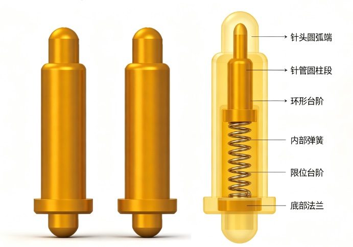
Pogo Pin Basics: Travel is determined by the internal length of the barrel available to house the spring; standard off-the-shelf products cannot be modified directly—one must switch specifications or customize the structure.
Pogo pin Total travel is the maximum distance the plunger can move within the barrel; the recommended working travel is 60%–70% of the total travel. Avoid compressing to the limit, as this causes rapid spring fatigue, loss of spring force, and a drastic reduction in lifespan.
I. Increase Pogo Pin Working Stroke Solutions
Solution 1: Select a standard part with longer travel (Recommended)
Choose an off-the-shelf pogo pin with a greater free height and total travel while maintaining the same outer diameter.
Example: Switch a φ1.5mm pin from 1.0mm travel to a 2.0mm or 3.0mm travel specification.
Trade-off: The total product height increases; the housing structure or PCB spacing requires redesign.
Solution 2: Counter-bored / Hollow plunger structure (Preferred for space constraints)
The tail of the plunger is hollowed out (counter-bored) to allow part of the spring to sit inside the plunger itself. This significantly increases spring length and travel without changing the overall height.
Advantages: No increase in overall height; achieves longer travel in limited space.
Disadvantages: Thinner plunger walls reduce current-carrying capacity; higher manufacturing costs; generally suitable for signal or low-current applications.
Solution 3: Increase barrel outer diameter, lengthen barrel, and lengthen spring
Maintain the same free height but increase the barrel's inner diameter to accommodate a longer spring.
Advantages: Allows for a thicker spring wire diameter, resulting in stable spring force and high-current capability.
Disadvantages: Increases the pitch (spacing); occupies more PCB area.
Solution 4: Custom-made elongated barrel and spring
II.Custom-machine a longer barrel and spring; travel distances of 5mm or more are achievable.
Note: For a given wire diameter, a longer spring results in a "softer" K-value (spring rate/slope); to maintain the original spring force, the spring wire thickness must be increased. II. Interrelated Changes in Key Pogo Pin Parameters
1. Pogo pin Spring Force Changes
With the same spring wire diameter, increasing the stroke length results in a longer spring and a lower spring constant (K-value); consequently, the spring force decreases for the same amount of compression.
To maintain the original force (gf), one must either increase the spring wire thickness or adjust the number of spring coils.
2. Pogo pin Contact Resistance
It is preferable to use a plunger with an angled tip (12–18° bevel) to ensure the side wall of the plunger maintains continuous contact with the inner wall of the barrel during compression. Using a flat tip for long strokes often leads to momentary signal interruptions or dynamic resistance fluctuations during the mid-compression phase.
3. Pogo pin Lifespan
Long-stroke springs undergo greater deformation with each compression cycle; if the operating point approaches the limit of the total stroke, fatigue life decreases significantly.
4. Risk of Pin Jamming
A longer stroke means a greater axial sliding distance for the plunger, requiring higher standards for the inner barrel wall's surface finish and coaxiality. Poor machining quality can lead to pin jamming or sluggish spring return.
III. Pogo Pin Design Rules
1. Working Stroke vs. Total Stroke
The total stroke represents the mechanical limit. Actual working compression should be controlled to 60–70% of the total stroke to provide a safety margin and prevent the spring from bottoming out due to the accumulation of assembly tolerances.
2. Assembly Tolerance Stack-up Calculation:
Required working stroke ≥ Sum of all component tolerances (housing, PCB, plastic parts, warpage) + Safety margin (0.1–0.2 mm).
3. Multi-pin Arrays:
When the stroke is increased—assuming the force of an individual pin remains constant—the total mating force rises; it is necessary to evaluate whether this might cause the PCB to bend or warp.
IV. Common Misconceptions About Pogo Pins
Do not grind or cut existing
pogo pins to increase the stroke: cutting destroys the internal stop mechanism and the angled conductive structure, directly leading to poor contact or pin jamming.
Do not compress long-stroke pogo pins to their full stroke limit during use: this causes permanent plastic deformation of the spring, leading to a significant drop in spring force after just a few cycles. V. Pogo Pin Selection and Consultation
1. Required total stroke and working stroke
2. Target spring force (gf) at the working compression point
3. Maximum current; signal or power application
4. Free height, mounting height, and outer diameter
5. Lifespan requirements (number of cycles) and gold plating thickness

 WhatsApp:+8613652508770