Solution for Instantaneous Power-Off of Pogo Pin
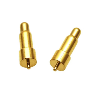
Solution for Instantaneous Power-Off of Pogo Pins During Drop Testing of Electronic Products
With the development of technology, the quality requirements for various electronic products are becoming increasingly stringent. Many engineers encounter the problem of power-off after product drops, leading to product malfunction—a rather troublesome issue.
After multiple verifications by our company's engineers, a good solution was found.
I. Root Cause of Instantaneous Power-Off of Pogo Pins During Drop Testing
Conductive Logic of a
Standard Pogo Pin with an Inclined Face (without Steel Ball):
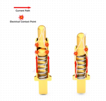
Current Path: Pin Head Contact ↔ Opposite Female Socket → Pin Outer Wall ↔ Pin Tube Inner Wall
Conduction relies on the continuous contact between the inclined face of the pin shaft and the inner wall of the pin tube.
Failure Mechanism under Drop Impact Conditions:
1. The product experiences a violent impact acceleration upon drop, causing the pin shaft to bounce rapidly and slightly axially within the pin tube; this is accompanied by lateral oscillation.
Axial runout: Impact causes the needle shaft to spring upward instantaneously, and the beveled surface of the needle shaft briefly detaches from the inner wall of the needle tube; Lateral oscillation: Multiple impacts from a drop cause the needle shaft to tilt, reducing the contact area of the beveled surfaces and even causing temporary separation; Once the conductive interface is temporarily separated, the original conductive path is broken; at this time, the current is forced to be conducted through the spring.
Spring contact is a point contact, with high impedance and unstable contact. Even slight vibrations or separation can cause impedance abrupt changes and instantaneous circuit breakage, which the equipment interprets as a power failure.
2. This is even more pronounced with ordinary reverse drilling Pogo; even with a conventional beveled needle, after the needle shaft briefly detaches from the inner wall of the needle tube under impact, the current is easily interrupted by the spring conducting the current.
Instantaneous interruption is not equivalent to permanent poor contact; it is a temporary separation of the conductive interface under dynamic impact.
II. Solution: Adopt a Pogo Pin with an internal gold-plated steel ball structure (a solution verified as effective by our Cnomax company)
1. Structural principle modification: Add a gold-plated steel ball between the beveled surface at the tail of the needle shaft and the spring.
A new stable conductive path:
Needle shaft body → Gold-plated steel ball → Needle tube inner wall
Conductivity no longer relies solely on the needle shaft's inclined surface directly contacting the needle tube.
2. Why the steel ball structure solves the problem of momentary breakage during drops
Adaptive compensation, continuously establishing a metallic conductive path
During a drop impact, the needle shaft experiences axial rebound and lateral oscillation; the steel ball, being a rolling contact component, can adaptively fine-tune its angle. Even if the needle shaft momentarily shifts up and down or tilts slightly, the steel ball can still simultaneously maintain close contact with the inclined surface at the tail of the needle shaft and the inner wall of the needle tube, always maintaining a stable metallic contact surface, ensuring the conductive circuit is not interrupted.
Isolation spring, preventing current from passing through the spring
In ordinary structures, under extreme conditions, current is forced to flow through the spring; with the addition of the steel ball, the main current is transmitted entirely through "needle shaft — steel ball — needle tube". The spring only provides mechanical axial pressure and no longer participates in conductivity, avoiding the risk of momentary breakage caused by unstable spring contact.
Multi-point contact, improved vibration and impact resistance
The steel ball and the inclined surface form a spherical-inclined contact, and the contact area has a self-positioning effect. Compared to simple beveled line contact, it offers stronger resistance to vibration and maintains conductivity even under multi-directional drops (six-sided drops).
3. Component Manufacturing Requirements
Steel Ball Material: High-hardness stainless steel balls; surface must be gold-plated (base nickel + top hard gold).
Purpose: To prevent steel ball oxidation, stabilize contact resistance, and avoid impedance increase after long-term use. Bare steel balls are prohibited.
Pin Shaft Tail Bevel: 35°~45° bevel recommended. The bevel should be polished and burr-free to ensure smooth contact with the steel ball.
Size Matching: The steel ball diameter, needle tube inner diameter, and pin shaft bevel depth are designed to match to ensure the steel ball does not jam or fall out under compression, and that extension and retraction are smooth and without needle jamming.
Spring Selection: Maintain the original reasonable elasticity. The spring is only responsible for applying pressure and does not participate in conduction.
4. Advantages and Disadvantages of this Solution
Advantages: Significant improvement in rectification effect; our company's actual tests show a direct reduction in the power failure issue caused by drops; Minimal structural modifications are required without significant changes to the overall machine structure, bracket adjustments, or preload stroke changes; Applicable to various docking scenarios for PCB and FPC female connectors; Better contact resistance consistency after long-term vibration and high/low temperature vibration testing.
Disadvantages: Increased material cost due to the addition of steel ball components, resulting in higher material costs than ordinary beveled Pogo Pins; however, the overall cost increase is not substantial.
Higher precision requirements are needed; poor control of the beveled pin shaft and steel ball dimensional tolerances can easily lead to pin jamming; For products with the same outer diameter, the internal space occupied by the steel ball is limited, requiring prior verification for products with extremely limited overall design height.
III. Pogo Pin Optimization Recommendations
Even with a steel ball structure Pogo, the following design elements can prevent failure under extreme operating conditions:
Sufficient static preload: The entire unit should have a static compression margin ≥ 0.3mm to reduce the maximum bounce stroke of the pin shaft.
Control the radial clearance between the pin shaft and the pin tube:** 0.005~0.008mm to suppress large lateral swing of the pin shaft.
If the mating end is an FPC flexible board:** Add a reinforcing steel sheet to the back of the FPC to prevent deformation of the female connector from pulling apart the contacts during drops.
Spring force: Match the spring force to the product weight, prioritizing spring force specifications of 100gf or higher to improve interface bonding pressure.
IV. Solution Verification Results:
This is a real-world case. The customer's smart electronic product was targeted at the elderly and children. During use, the product was frequently dropped, causing it to lose power and malfunction.
They ultimately contacted Cnomax. After our engineers added gold-plated steel balls inside the Pogo pin, this problem was resolved, and the power outages have not occurred since.
The following is a comparison of the improved versions, provided for reference by electronic engineers. We hope it will be helpful in your designs.
Standard slanted Pogo pin: Impact bounce → the slanted pin shaft detaches from the inner wall of the needle tube → the conductive path is interrupted → momentary power loss.
Pogo pin with built-in gold-plated steel ball: Regardless of slight movement or oscillation of the pin shaft, the gold-plated steel ball continuously bridges the gap between the pin shaft and the needle tube, maintaining a continuous main circuit. Power loss will not occur upon impact.

 WhatsApp:+8613652508770