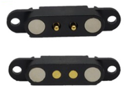
How does the magnetic connector work ?
Magnetic connectors, such as Apple’s MagSafe, USB-C magnetic adapters, and industrial-grade magnetic couplings, have revolutionized the way devices connect for charging, data transfer, and modular assembly. Their seamless usability and safety mechanisms rely on a sophisticated interplay of magnetism, electrical engineering, and mechanical design. Below, we dissect their working principles systematically.
1. Magnetic Force: The Foundation of Alignment and Attachment
1.1 Magnet Configuration and Polarity Design
Magnetic connectors consist of two halves: a plug (attached to the cable) and a receptacle (embedded in the device). Both halves integrate permanent magnets, typically made of neodymium (NdFeB) due to their high magnetic strength and compact size. These magnets are arranged in specific patterns to ensure optimal alignment and attachment:
Circular or Symmetric Layout: In designs like MagSafe, magnets form a circular array around the central electrical contacts. This creates a radial magnetic field that guides the plug into the correct position.
Polarity Optimization: The north and south poles of the magnets are strategically alternated to ensure that the plug attaches only in the correct orientation. For example, a "keyed" design prevents reverse insertion, while rotationally symmetric layouts (e.g., circular connectors) allow 360-degree attachment.
1.2 Self-Alignment Mechanism
The magnetic field generates a torque that automatically rotates and slides the plug into alignment. This eliminates the need for precise manual positioning, a critical advantage in low-visibility scenarios (e.g., plugging in a device behind furniture).
1.3 Magnetic Force Thresholds
The strength of the magnets is carefully calibrated:
Strong enough** to maintain a secure connection during normal use.
Weak enough to detach safely under excessive force (e.g., tripping over a cable), preventing device damage.
For instance, MagSafe connectors typically require 1–2 kg of pull force to disconnect.
2. Electrical Contact Design: Bridging Power and Data
2.1 Conductive Contact Types
Magnets themselves are non-conductive, so separate electrical contacts are required to transmit power or data. Common designs include:
Spring-Loaded Pogo Pins: These compressible pins maintain consistent contact pressure even with minor misalignment. Gold plating reduces oxidation and ensures low electrical resistance.
Elastic Metal Contacts: Bent metal strips or leaf springs provide similar functionality, often used in slim-profile connectors.
2.2 Multi-Channel Contact Arrangements
The number and layout of contacts depend on the connector’s purpose:
Power-Only Connectors: Two contacts (positive and negative) suffice for charging.
Data-Power Hybrid Connectors: Additional pins handle data transmission (e.g., USB 2.0/3.0, Thunderbolt). For example, a USB-C magnetic adapter may include 12–24 contacts to support high-speed data, video output, and Power Delivery (PD).
2.3 Sequential Engagement and Short-Circuit Prevention
To avoid sparks or short circuits during connection/disconnection, advanced connectors use:
Staggered Contact Lengths: Ground pins make contact first and break last, stabilizing the electrical connection.
Insulating Barriers: Non-conductive materials separate adjacent contacts until fully engaged.
3. Safety and Reliability Mechanisms
3.1 Mechanical Safety Features
Breakaway Mechanism: Magnetic detachment protects against accidental drops. For example, MagSafe disconnects at ~5–10 N of lateral force.
Dust/Water Resistance: Sealing gaskets or hydrophobic coatings (e.g., IP67-rated connectors) prevent debris or liquid ingress.
3.2 Electrical Safety Systems
Overcurrent Protection: Embedded ICs monitor current flow and cut power if thresholds are exceeded (e.g., >5A for USB-PD).
Temperature Sensors: Thermistors detect overheating, triggering shutdown to prevent damage to batteries or circuits.
Voltage Regulation: Adaptive voltage negotiation (e.g., USB Power Delivery) ensures compatibility across devices.
3.3 Electromagnetic Interference (EMI) Mitigation
Magnetic fields can interfere with nearby sensors (e.g., Hall effect sensors) or storage devices. Solutions include:
Shielding: Ferrite layers or mu-metal enclosures contain magnetic flux.
Frequency Modulation: Data signals are encoded at frequencies less susceptible to magnetic noise.
4. Material Science and Durability
4.1 Magnet Selection and Longevity
Neodymium Magnets: Offer the highest energy density (up to 52 MGOe) but require nickel or epoxy coatings to prevent corrosion.
Temperature Resistance: High-grade N52 magnets retain strength up to 80°C, suitable for most consumer electronics.
4.2 Contact Materials and Wear Resistance
Gold Plating: 0.2–0.5 μm gold layers on contacts minimize resistance (≈10–50 mΩ) and resist oxidation.
Palladium or Rhodium Coatings: Used in high-end connectors for extreme durability (>100,000 mating cycles).
4.3 Structural Materials
Reinforced Plastics: Glass-filled nylon or PBT withstand repeated mechanical stress.
Metal Alloys: Aluminum or stainless steel housings provide EMI shielding and ruggedness.
5. Applications and Evolving Technologies
5.1 Consumer Electronics
Smartphones and Laptops: MagSafe (Apple), magnetic charging docks (Samsung).
Wearables: Magnetic charging rings for smartwatches (e.g., Apple Watch).
5.2 Industrial and Medical Systems
Robotic Tool Changers: Magnetic connectors enable rapid end-effector swaps in automated assembly lines.
Implantable Devices: Hermetically sealed magnetic ports for pacemakers or neural implants.
5.3 Future Innovations
Self-Cleaning Contacts: Ultrasonic vibration to remove oxidation or debris.
Smart Polarity Reversal: Auto-detection of plug orientation via Hall effect sensors.
Wireless Integration: Hybrid magnetic-inductive charging (e.g., Qi2 Magnetic Profile).
Conclusion:Magnetic connectors exemplify the synergy between physics and engineering. By leveraging precise magnetic fields, robust contact materials, and intelligent safety systems, they deliver unparalleled convenience and reliability. However, challenges remain in balancing miniaturization, cost, and compatibility—especially as devices demand higher power (e.g., 240W USB-PD) and faster data rates (e.g., USB4 40 Gbps). Future advancements may integrate AI-driven power management or biodegradable materials for sustainability, ensuring magnetic connectors remain a cornerstone of modern connectivity.
if you need to know more about Pogo pin or Magnetic Connector,please contact us,thank you
